
Apache Airflow Complete System Architecture
Understanding Distributed Orchestration Mechanics
Apache Airflow is a distributed, platform-agnostic workflow orchestration engine designed to programmatically author, schedule, and monitor data pipelines. Understanding the internal architecture, component responsibilities, and network communication pathways is essential for deploying production clusters, troubleshooting execution bottlenecks, and designing scalable workflows.
1. High-Level Architectural Topology
At its foundational level, an Apache Airflow environment is separated into three distinct operational planes: the Control Plane, the Execution Plane, and the Storage Plane. Each plane contains modular daemons and persistence mechanisms that communicate via database state, message queues, and network file systems.
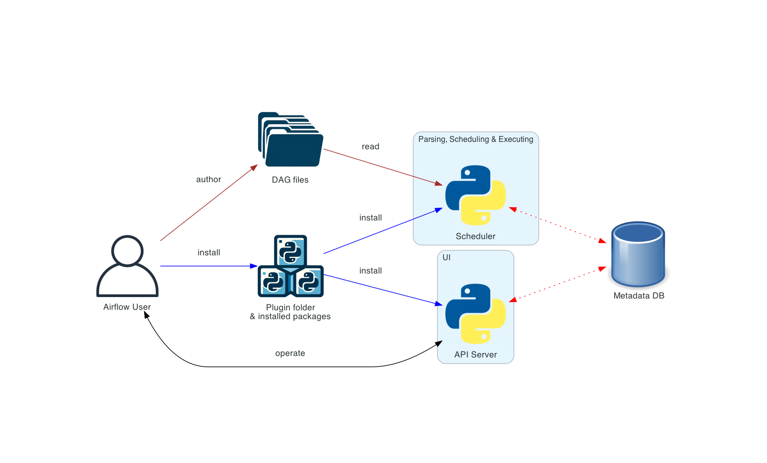
Basic Single-Node Architecture
In local development or lightweight testing environments, all architectural components execute within a single physical host or container. A single-node deployment typically utilizes the SequentialExecutor or LocalExecutor, where task execution occurs directly within local subprocesses rather than across distributed network nodes.
Distributed Production Architecture
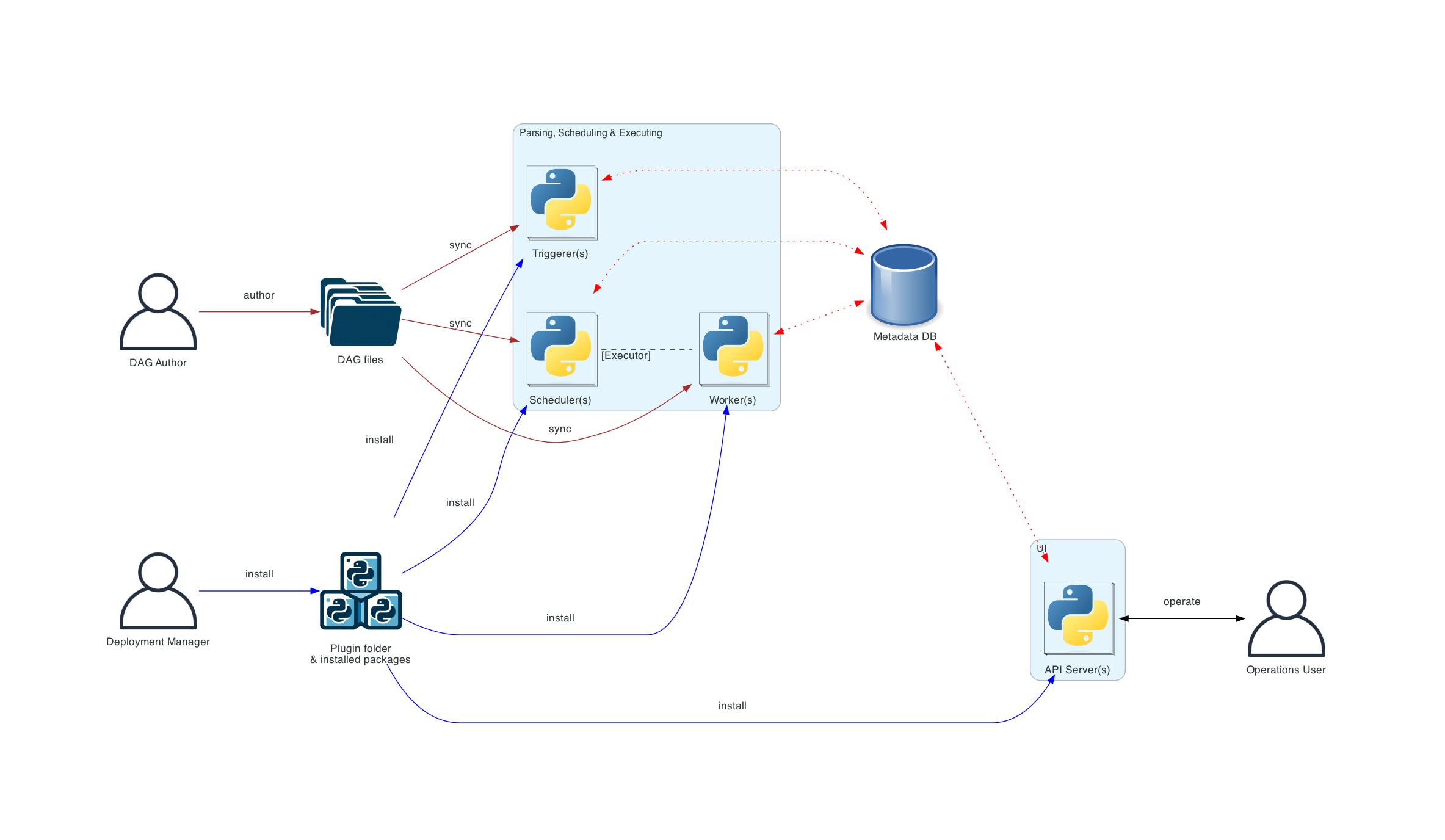
In enterprise production deployments, Airflow scales horizontally across multiple compute instances. The Control Plane runs on dedicated server instances (often with High Availability schedulers), while the Execution Plane spans dynamic worker pools orchestrated via distributed queuing systems like Celery or container platforms like Kubernetes.
End-to-End Component Topology Map
The following diagram illustrates the structural relationships and boundary layers between all core Airflow system components:
graph TB
    subgraph Control_Plane ["Control Plane (Orchestration & UI)"]
        UI["Webserver<br/>(Flask + Gunicorn HTTP Server)"]
        SCHED["Scheduler<br/>(DAG File Processor & Loop Engine)"]
        TRIG["Triggerer<br/>(Async Deferral Event Daemon)"]
    end

    subgraph Storage_Plane ["Storage & Persistence Plane"]
        DB[("Metadata Database<br/>(PostgreSQL / MySQL / SQLite)")]
        DAGS["DAGs Directory<br/>(Synchronized Python Scripts)"]
        LOGS["Remote Log Storage<br/>(AWS S3 / GCS / CloudWatch)"]
    end

    subgraph Execution_Plane ["Execution Plane (Distributed Compute)"]
        EXEC["Executor<br/>(Task Distribution Strategy Engine)"]
        BROKER[["Message Broker<br/>(Redis / RabbitMQ Queue)"]]
        W1["Celery Worker Node 1<br/>(Task Execution Process)"]
        W2["Celery Worker Node 2<br/>(Task Execution Process)"]
        W3["Celery Worker Node N<br/>(Task Execution Process)"]
    end

    UI -->|"Queries state & metadata"| DB
    UI -->|"Reads DAG scripts"| DAGS
    UI -->|"Fetches execution logs"| LOGS

    SCHED -->|"Reads & parses DAGs"| DAGS
    SCHED -->|"Writes DAG runs & task states"| DB
    SCHED -->|"Submits queued tasks"| EXEC

    TRIG -->|"Monitors deferred task state"| DB

    EXEC -->|"Pushes task payloads"| BROKER
    BROKER -->|"Consumes task messages"| W1
    BROKER -->|"Consumes task messages"| W2
    BROKER -->|"Consumes task messages"| W3

    W1 -->|"Reads DAG source"| DAGS
    W2 -->|"Reads DAG source"| DAGS
    W3 -->|"Reads DAG source"| DAGS

    W1 -->|"Updates task heartbeat & status"| DB
    W2 -->|"Updates task heartbeat & status"| DB
    W3 -->|"Updates task heartbeat & status"| DB

    W1 -->|"Uploads execution output"| LOGS
    W2 -->|"Uploads execution output"| LOGS
    W3 -->|"Uploads execution output"| LOGS

    style Control_Plane fill:#f8fafc,stroke:#cbd5e1,color:#0f172a
    style Storage_Plane fill:#f8fafc,stroke:#cbd5e1,color:#0f172a
    style Execution_Plane fill:#f8fafc,stroke:#cbd5e1,color:#0f172a
    style UI fill:#00c7d4,stroke:#009ea8,color:#fff
    style SCHED fill:#017cee,stroke:#015bb5,color:#fff
    style TRIG fill:#7b1fa2,stroke:#4a148c,color:#fff
    style DB fill:#e43921,stroke:#c02a10,color:#fff
    style DAGS fill:#607d8b,stroke:#455a64,color:#fff
    style LOGS fill:#607d8b,stroke:#455a64,color:#fff
    style EXEC fill:#ff9800,stroke:#f57c00,color:#fff
    style BROKER fill:#f59e0b,stroke:#d97706,color:#fff
    style W1 fill:#00ad46,stroke:#008a38,color:#fff
    style W2 fill:#00ad46,stroke:#008a38,color:#fff
    style W3 fill:#00ad46,stroke:#008a38,color:#fff
2. Comprehensive Component Deep Dive
The Scheduler (airflow scheduler)
The Scheduler is the primary orchestrator of the Airflow ecosystem. It runs as a continuous background daemon responsible for parsing Python DAG files, evaluating scheduling criteria, generating execution runs, and submitting tasks to worker nodes.
Core Responsibilities
- DAG Parsing via DagFileProcessorManager: The scheduler continuously scans the filesystem directory defined in
dags_folder. It spawns isolated subprocesses (DagFileProcessor) to parse Python scripts, extract DAG definitions, and serialize structural metadata into the Metadata Database. This ensures that user code syntax errors do not crash the master scheduler daemon. - Scheduling Loop: The scheduling engine loops continuously over all active DAGs in the database. When a DAG's schedule interval arrives, the scheduler creates a
DagRunrecord and populates its associatedTaskInstancerecords with an initial state ofNoneorScheduled. - Dependency Evaluation: In each loop iteration, the scheduler evaluates task dependencies (such as upstream execution completion, trigger rules, and branching logic). When all prerequisites are satisfied, the task instance state transitions to
Queued. - Task Submission: Queued task instances are pushed from the scheduler to the active Executor queue, waiting for compute resources to become available.
- Heartbeat & Orphan Detection: The scheduler periodically emits a heartbeat timestamp to the database. Simultaneously, it checks for orphaned worker jobs or stalled task instances that failed to report heartbeats, marking them as failed or rescheduling them according to retry policies.
High Availability (HA) Schedulers
In Airflow 2.0+, organizations can run multiple concurrent scheduler instances for fault tolerance and load balancing. To prevent two schedulers from simultaneously scheduling the exact same task instance, Airflow utilizes database row-level locking (SELECT ... FOR UPDATE in SQL). When a scheduler examines a DagRun or TaskInstance, it acquires an exclusive lock on that database row until the state transition is committed.
The Webserver (airflow webserver)
The Webserver serves as the interactive frontend control panel and REST API interface for administrators and data engineers. Built on Python's Flask framework and served via Gunicorn (Green Unicorn WSGI HTTP server), it provides visual dashboards for monitoring pipeline health, debugging task failures, and managing system security.
Why We Use It
- Pipeline Monitoring & Intervention: Users can visually inspect DAG execution progress across standard views (Grid View, Graph View, Gantt Chart, and Calendar View), trigger manual pipeline runs, clear failed task states to initiate re-runs, and inspect real-time execution logs.
- Security & Role-Based Access Control (RBAC): Integrated with Flask-AppBuilder, the webserver manages user authentication, enterprise LDAP/OAuth integration, and granular permissions (e.g., restricting data analysts to read-only views of specific DAG folders while granting full operational control to engineering leads).
- Decoupled Architecture: Notice that the Webserver does not execute data processing tasks or communicate directly with worker compute nodes. It operates entirely by reading serialized DAG definitions from shared storage and querying historical task states from the Metadata Database. If the webserver experiences downtime, background DAG execution continues without interruption.
The Metadata Database
The Metadata Database is the relational database engine that serves as the single source of truth for all system state, configuration parameters, and historical logs across the Airflow cluster.
What It Stores
The database maintains structured tables mapping the entire operational history:
dag: Serialized definitions, schedules, ownership tags, and active status.dag_run: Historical and ongoing execution instances keyed by logical execution date.task_instance: Real-time state of every individual task (QUEUED,RUNNING,SUCCESS,FAILED,UPSTREAM_FAILED), retry counts, hostname assignments, and execution timestamps.xcom: Cross-communication key-value payloads passed between executing tasks.variable&connection: Global environmental parameters and encrypted external database/API connection credentials.log&job: Audit trails of user actions and daemon heartbeat registries.
SQLite Deep Dive: Why We Use It & Why It Fails in Production
Airflow includes built-in support for SQLite, a file-based relational database engine.
- Why We Use SQLite: When developers execute
airflow standaloneon a local laptop, Airflow initializes an SQLite file (airflow.db) in the local home directory. This allows instant local experimentation and DAG prototyping without requiring Docker containers or external database server installations. - Why SQLite Fails in Production: SQLite uses file-level locking for database transactions. When a process writes to an SQLite database, it locks the entire file, preventing any other process from reading or writing until the transaction completes. In a distributed or multi-threaded Airflow setup, the Scheduler, Webserver, Triggerer, and concurrent worker processes constantly attempt simultaneous database reads and writes. With SQLite, these concurrent requests collide, resulting in operational failures with
sqlite3.OperationalError: database is lockedand severe database corruption. Consequently, SQLite can only be used with the single-processSequentialExecutorand must never be deployed in multi-user or production environments.
Enterprise Database Engines: PostgreSQL & MySQL
For enterprise deployments, Apache Airflow requires PostgreSQL (highly recommended by the Airflow PSC) or MySQL running InnoDB.
- These enterprise engines implement row-level locking (via MVCC — Multi-Version Concurrency Control), allowing hundreds of concurrent worker processes and High Availability schedulers to read and update task states simultaneously without blocking tables.
- Airflow communicates with the relational database through SQLAlchemy, a Python Object Relational Mapper (ORM) that manages connection pooling, transaction rollback safety, and dialect abstraction.
The Executor (airflow.executors)
A common misconception is that an Airflow Executor is an independent server node or compute cluster. In reality, an Executor is a software mechanism configured internally within the Scheduler daemon. The Executor defines the strategy for where and how task instances are submitted for execution.
Comprehensive Executor Comparison
| Executor Type | Execution Mechanism | Concurrency Model | Infrastructure Requirements | Best Fit Use Case |
|---|---|---|---|---|
| SequentialExecutor | Single local Python process inside the scheduler | Exactly 1 task at a time (zero parallelism) | None (works with SQLite file) | Local development, syntax debugging, and initial tutorials |
| LocalExecutor | Local multiprocessing subprocesses on the scheduler host | Multi-task parallelism limited by host CPU/Memory | Single server with PostgreSQL / MySQL | Small-to-medium teams with moderate, predictable workload volumes |
| CeleryExecutor | Distributed message queue dispatching to remote Celery workers | Unlimited horizontal scaling across worker nodes | Message Broker (Redis/RabbitMQ) + Result Backend DB | Enterprise production clusters requiring steady worker pools and rapid task startup |
| KubernetesExecutor | Ephemeral Kubernetes Pod launched per individual task instance | Highly elastic, dynamic container scaling | Kubernetes cluster with RBAC pod creation permissions | Cloud-native workloads requiring strict container isolation, custom image dependencies, and zero idle compute costs |
| CeleryKubernetesExecutor | Hybrid routing via task queue assignment (queue='kubernetes') |
Combined Celery worker pools + ephemeral K8s pods | Full Celery infrastructure + Kubernetes cluster | Complex enterprise environments with both high-frequency lightweight tasks and heavy, specialized batch jobs |
Deep Dive: The Celery Executor Mechanics
The CeleryExecutor is the industry standard for robust, low-latency distributed task execution. It builds upon Celery, an asynchronous distributed task queue written in Python.
When configured with CeleryExecutor, the architectural topology introduces two critical infrastructure components:
- The Message Broker (Redis or RabbitMQ): Acts as the intermediary task queue. When the Scheduler marks a task instance as ready, the CeleryExecutor serializes the task command payload (e.g.,
airflow tasks run dag_id task_id execution_date) and pushes it as a message onto the broker queue. - Celery Worker Nodes: Independent server machines or containers running the
airflow celery workerdaemon. Worker processes continuously poll the Message Broker queue. When a task message appears, a worker node pops the message from the queue, executes the command within a local worker subprocess, and writes the final execution status back to the database.
Deep Dive: The Kubernetes Executor Mechanics
The KubernetesExecutor transforms the Airflow Scheduler into a Kubernetes native controller.
- Instead of pushing messages to a static pool of Celery workers, the Scheduler makes direct REST API calls to the Kubernetes API server whenever a task is ready to run.
- For each individual task instance, Airflow dynamically provisions an ephemeral Kubernetes Pod using a specified Docker image, CPU/memory request allocations, and environment variables defined in a Pod Template File.
- Once the task finishes execution (either successfully or with an error), the Pod terminates and is garbage collected from the cluster. This ensures perfect resource utilization (zero idle worker costs) and complete dependency isolation between conflicting Python environments.
The Triggerer (airflow triggerer)
Introduced in Apache Airflow 2.2+, the Triggerer is an independent background daemon designed to execute Deferrable Operators (also known as Async Operators or Smart Sensors).
Why We Use the Triggerer: The Sensor Bottleneck
In traditional Airflow architectures, a Sensor task (such as S3KeySensor waiting for a file to land in AWS S3 or SqlSensor waiting for a database table update) operates synchronously. When a sensor runs, it occupies a full worker compute slot in the Executor, polling the external system every few seconds or minutes. If a pipeline contains 50 sensors waiting for external data delivery over a 4-hour window, those 50 sensors consume 50 worker slots continuously, blocking other productive processing tasks and driving up cloud compute expenses.
Deferrable Operator Architecture
The Triggerer eliminates this compute bottleneck using Python's asynchronous event loop (asyncio):
- Task Deferral: When a deferrable operator initiates, it performs an initial check. If the required condition is not met, the task raises an internal
TaskDeferredexception, registering a lightweight async event trigger in the Metadata Database and immediately releasing its worker slot back to the Executor pool. - Async Event Polling: The Triggerer daemon queries the Metadata Database for active triggers and loads them into an internal asynchronous event loop. A single Triggerer process can monitor tens of thousands of concurrent network connections, webhooks, or cloud storage polling loops using minimal CPU and memory.
- Resumption Hand-off: When the Triggerer detects that the external condition is satisfied (e.g., the AWS S3 file has arrived), it fires a completion event and updates the task instance state in the Metadata Database back to
Scheduled. The Scheduler picks up the resumed task and pushes it back to an Executor worker slot to execute the remaining downstream pipeline logic.
The DAG Directory & Storage Layer
The DAG Directory (dags_folder) is the filesystem path where data engineers deploy their Python workflow scripts. Because Airflow is a distributed system, the exact same DAG Python source files must be continuously synchronized across three distinct architectural planes:
- The Scheduler: Needs source files to parse DAG structures and evaluate intervals.
- The Webserver: Needs source files to display code snippets, render docstrings, and generate visual Graph/Grid views.
- Worker Nodes: Need source files to execute the actual Python operator code, hooks, and task callbacks during pipeline runs.
Distributed Storage Synchronization Strategies
To maintain code consistency across distributed server instances, production clusters employ structured storage patterns:
- Network File System (NFS) / AWS EFS / Google Cloud Filestore: Mounting a shared POSIX-compliant network volume across all Scheduler, Webserver, and Worker nodes. When CI/CD pipelines push code to the shared volume, all nodes see the changes instantly.
- Git-Sync Sidecar Containers: In Kubernetes environments, each Airflow pod runs a lightweight container alongside the main Airflow daemon that continuously polls a remote Git repository (e.g., every 30 seconds) and pulls the latest DAG commits into a shared container volume.
- Baked Docker Images: Immutably bundling DAG Python scripts directly into the custom Airflow Docker image during the CI/CD build process. While requiring a container redeployment for DAG changes, this pattern eliminates filesystem sync lag and guarantees absolute code version consistency across the cluster.
The Logging Architecture
Task execution logs are vital for debugging pipeline failures, monitoring data processing volumes, and satisfying audit compliance. Airflow separates log generation from log presentation through a decoupled storage workflow.
How Logs Are Handled Across Components
- Local Worker Generation: When a worker node executes a task instance, it writes standard output (
stdout) and standard error (stderr) streams directly to its local filesystem under the directory specified bybase_log_folder(e.g.,/opt/airflow/logs/dag_id/run_id/task_id/attempt.log). - Remote Storage Persistence: In distributed architectures, worker containers are often ephemeral and terminate after task completion. To prevent log loss, workers configure a Remote Logging Backend (such as Amazon S3, Google Cloud Storage, or Azure Blob Storage). As soon as a task instance completes or fails, the worker process automatically uploads the local log file to the remote cloud object storage bucket.
- Webserver Log Serving: When a user clicks a task instance in the Airflow UI and selects the "Log" tab, the Webserver does not attempt to contact the worker node that executed the task. Instead, it checks the local log directory; if the log is missing locally, the Webserver uses the configured cloud credentials to fetch the log file directly from the remote S3/GCS bucket and streams it seamlessly to the user's browser.
3. End-to-End Task Execution Lifecycle Sequence
Understanding how these components interact in chronological order clarifies the internal mechanics of Airflow orchestration. The sequence diagram below traces the complete lifecycle of a single task instance from initial DAG parsing through execution completion and remote log persistence:
sequenceDiagram
    autonumber
    actor Dev as Data Engineer
    participant DAGS as DAG Directory
    participant Sched as Scheduler Daemon
    participant DB as Metadata Database
    participant Exec as Celery Executor
    participant Broker as Redis / RabbitMQ
    participant Worker as Celery Worker Node
    participant Logs as Remote S3 / GCS Logs
    participant UI as Webserver UI

    Dev->>DAGS: Deploy new Python DAG script
    loop Every dag_dir_list_interval (300s)
        Sched->>DAGS: Scan directory & parse Python scripts
        Sched->>DB: Serialize DAG structure & schedule intervals
    end

    Note over Sched,DB: Schedule Interval Arrives
    Sched->>DB: Create DagRun record (State: RUNNING)
    Sched->>DB: Create TaskInstance records (State: SCHEDULED)

    loop Scheduling Loop (Continuous)
        Sched->>DB: Query SCHEDULED tasks with satisfied dependencies
        Sched->>DB: Update TaskInstance state to QUEUED
        Sched->>Exec: Submit queued TaskInstance payload
    end

    Exec->>Broker: Push serialized task execution command message
    Note over Broker,Worker: Worker Polling Queue
    Worker->>Broker: Pop task message from queue
    Worker->>DB: Update TaskInstance state to RUNNING (assign hostname)

    Worker->>DAGS: Read DAG Python script for execution logic
    Note over Worker: Execute Operator / Hook / Data Transformation

    alt Task Execution Succeeds
        Worker->>DB: Update TaskInstance state to SUCCESS
        Worker->>Logs: Upload local execution logs to Remote Cloud Storage
    else Task Execution Fails
        Worker->>DB: Update TaskInstance state to UPSTREAM_FAILED or UP_FOR_RETRY
        Worker->>Logs: Upload failure tracebacks to Remote Cloud Storage
    end

    Dev->>UI: Open Airflow Web Dashboard & click TaskInstance
    UI->>DB: Fetch task status, execution dates, and metadata
    UI->>Logs: Retrieve remote log file from S3 / GCS
    UI-->>Dev: Render visual Grid status and stream execution logs
4. Engineering Configuration Code Snippets
Snippet 1: Configuring Database Connections & Concurrency (airflow.cfg)
The [database] and [core] sections of airflow.cfg govern how Airflow connects to its state store and manages concurrency. Notice the transition from SQLite to PostgreSQL for production readiness:
# =====================================================================
# CORE ENGINE CONFIGURATION
# =====================================================================
[core]
# Specify the filesystem path where DAG Python files are stored
dags_folder = /opt/airflow/dags

# Specify the execution engine strategy
# Options: SequentialExecutor (default dev), LocalExecutor, CeleryExecutor, KubernetesExecutor
executor = CeleryExecutor

# Specify the timezone for scheduling intervals (UTC recommended for distributed systems)
default_timezone = utc

# Specify the maximum number of concurrent task instances allowed across the entire cluster
parallelism = 32

# Specify the maximum number of active DAG runs allowed per individual DAG definition
max_active_runs_per_dag = 16


# =====================================================================
# METADATA DATABASE CONFIGURATION
# =====================================================================
[database]
# DEV/TEST ONLY: SQLite file connection string (prohibits concurrency)
# sql alchemy conn = sqlite:////root/airflow/airflow.db

# PRODUCTION: PostgreSQL connection string using psycopg2 driver
# Format: postgresql+psycopg2://<user>:<password>@<host>:<port>/<database name>
sql_alchemy_conn = postgresql+psycopg2://airflow_user:SuperSecurePass123@postgres-cluster.internal:5432/airflow_db

# Enable SQLAlchemy connection pooling to prevent database connection exhaustion under heavy load
sql_alchemy_pool_size = 5
sql_alchemy_max_overflow = 10
sql_alchemy_pool_recycle = 1800

# Specify the database schema (useful for shared database clusters)
sql_alchemy_schema = public
Snippet 2: Setting Up Distributed Celery Architecture (airflow.cfg)
When deploying the CeleryExecutor, you must configure the communication bridge between the Scheduler and remote worker nodes:
# =====================================================================
# CELERY EXECUTOR CONFIGURATION
# =====================================================================
[celery]
# The Message Broker URL where the Scheduler pushes queued task messages
# Redis Format: redis://:<password>@<host>:<port>/<database number>
# RabbitMQ Format: amqp://<user>:<password>@<host>:<port>/<virtual host>
broker_url = redis://:RedisAuthToken99@redis-master.cache.internal:6379/0

# The Result Backend URL where Celery workers write immediate task execution state answers
# Typically points to the same PostgreSQL metadata database or a dedicated Redis instance
result_backend = db+postgresql://airflow_user:SuperSecurePass123@postgres-cluster.internal:5432/airflow_db

# The number of concurrent worker processes spawned per individual Celery worker machine
worker_concurrency = 16

# The name of the default Celery queue where tasks are sent if no custom queue is specified in the DAG
default_queue = default

# Enable strict JSON serialization for secure message queue transmission
celery_config_options = airflow.config_templates.default_celery.DEFAULT_CELERY_CONFIG
Snippet 3: Designing Deferrable Operators for Triggerer Architecture (Python Script)
The following code demonstrates how to implement an asynchronous Deferrable Sensor within a DAG. This pattern hands off execution to the Triggerer daemon, freeing worker compute slots during long-duration external polling:
"""
Enterprise Deferrable Sensor DAG Architecture
Demonstrates async task hand-off to the Airflow Triggerer daemon to optimize worker compute utilization.
"""

from datetime import datetime, timedelta
from airflow import DAG
from airflow.providers.amazon.aws.sensors.s3 import S3KeySensor
from airflow.operators.python import PythonOperator

# 1. Define robust DAG default arguments with exponential backoff retry policies
default_args = {
    "owner": "data_engineering_team",
    "depends_on_past": False,
    "email_on_failure": True,
    "email": ["alerts@enterprise.com"],
    "retries": 3,
    "retry_delay": timedelta(minutes=5),
    "retry_exponential_backoff": True,
    "max_retry_delay": timedelta(minutes=30),
}

# 2. Initialize the Directed Acyclic Graph context
with DAG(
    dag_id="event_driven_s3_triggerer_pipeline",
    default_args=default_args,
    description="Polls AWS S3 asynchronously using the Triggerer daemon before launching downstream ETL",
    schedule_interval="0 6 * * *",  # Execute daily at 06:00 UTC
    start_date=datetime(2026, 1, 1),
    catchup=False,
    max_active_runs=1,
    tags=["architecture", "deferrable", "async"],
) as dag:

    # 3. Step 1: Deferrable S3 Sensor
    # Setting deferrable=True instructs the operator to register a Trigger in the DB
    # and immediately vacate its Celery/Kubernetes worker compute slot.
    wait_for_s3_extract = S3KeySensor(
        task_id="async_wait_for_daily_extract",
        bucket_key="s3://enterprise-data-lake/raw/daily_extract_*.parquet",
        wildcard_match=True,
        bucket_name=None,  # Bucket name is parsed directly from URI
        aws_conn_id="aws_default",
        poke_interval=60,  # Triggerer checks condition every 60 seconds
        timeout=60 * 60 * 4,  # Timeout after 4 hours of async polling
        deferrable=True,  # <--- CRITICAL ARCHITECTURAL FLAG: Activates Triggerer hand-off
    )

    # 4. Step 2: Downstream Transformation Logic
    # Once the Triggerer detects the S3 file, this task is pushed back to the Executor queue.
    def _execute_downstream_transformation(**context):
        logical_date = context["logical_date"].strftime("%Y-%m-%d")
        print(f"S3 extract verified by Triggerer. Launching spark ETL for date: {logical_date}")
        # Insert PySpark / Snowflake transformation invocation logic here
        return f"ETL successfully initiated for {logical_date}"

    process_data_pipeline = PythonOperator(
        task_id="launch_spark_transformation",
        python_callable=_execute_downstream_transformation,
    )

    # 5. Define topological execution dependencies
    wait_for_s3_extract >> process_data_pipeline
5. Architectural Summary & Best Practices Checklist
When designing or reviewing an Apache Airflow architecture, adhere to the following enterprise best practices:
- Never use SQLite or SequentialExecutor in production: Upgrade immediately to PostgreSQL/MySQL and Celery/Kubernetes Executors to prevent file locking corruption and enable multi-task parallelism.
- Isolate the Control Plane from the Execution Plane: Deploy the Webserver and Scheduler on dedicated compute instances separate from worker nodes so that heavy data processing workloads do not starve orchestration daemons of CPU or memory.
- Enable Scheduler High Availability (HA): Run at least two Scheduler replicas connected to the same PostgreSQL database to eliminate the single point of failure in pipeline orchestration.
- Adopt Deferrable Operators for Long-Running Wait Tasks: Activate the Triggerer daemon and convert standard sensors to deferrable (
deferrable=True) to prevent worker compute slot exhaustion. - Decouple Log Storage: Configure AWS S3, Google Cloud Storage, or Azure Blob as the remote logging backend so that ephemeral worker containers can terminate safely without losing execution audit trails.